

-
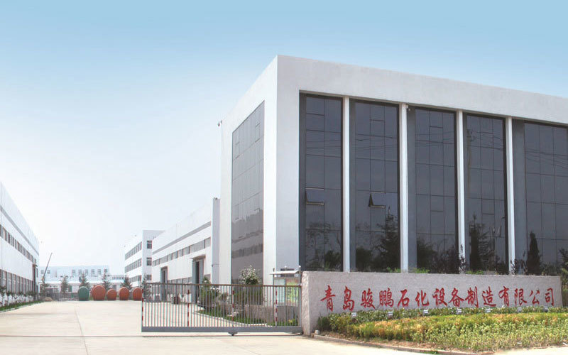
About UsQingdao Junpeng Petrochemical Equipment Manufacturing Co., Ltd. was established on February 10, 2010 with a registered capital of 51 million yuan. It is located in the beautiful tourist city of Qingdao.
-
ProductsQingdao Junpeng Petrochemical Equipment Manufacturing Co., Ltd. was established on February 10, 2010 with a registered capital of 51 million yuan. It is located in the beautiful tourist city of Qingdao.
Products
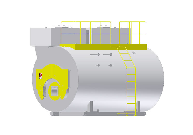
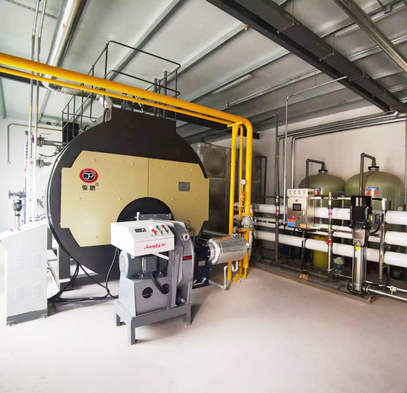
Organic heat transfer fluid (thermal oil boiler)
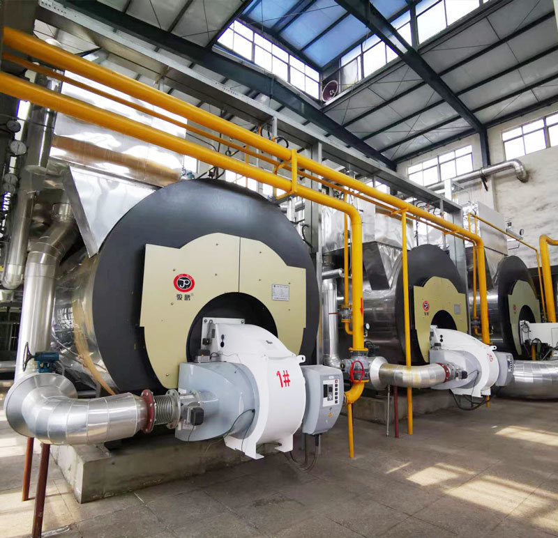
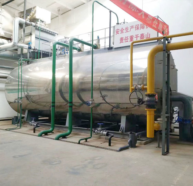
An organic thermal fluid heater is a new type of special boiler, also known as a heat transfer oil furnace. It has low-pressure, high-temperature operating characteristics, and its heating temperature can reach 340℃ in the liquid phase or 400℃ in the gas phase. Organic thermal fluid heating can be used in various production scenarios where uniform and stable heating is required and direct flame heating is not allowed, with process heating temperatures between 150℃ and 380℃. A horizontal oil/gas-fired organic thermal fluid heater uses oil and gas as fuel and heat transfer oil as the medium. It utilizes a hot oil circulation pump to force the medium to circulate in the liquid phase, transferring heat energy to the heat-using equipment before returning to the heater for reheating. It achieves high operating temperatures at low pressures and allows for high-precision control of the medium's operation. The system has high thermal efficiency, and due to its modular overall installation, operation and maintenance are convenient. It is a safe, efficient, and energy-saving ideal heating equipment. Fuel, after ignition by the burner, produces high-temperature flames that enter the inner coil to form a radiation heating surface. After passing through the rear of the inner coil, it rotates 180° and enters the annulus between the inner and outer tubes to form a convection heating surface. Then, it enters the second annulus between the middle and outer coils at the front of the annulus. Finally, it is discharged into the atmosphere through the chimney at the rear of the second annulus.
Category:
Oilfield Heating Boiler
Keywords:
Boiler Equipment

Phone:
Email:
Online Message
Product Description
1.1 Introduction to Organic Heat Transfer Fluid Heater (Thermal Oil Heater)
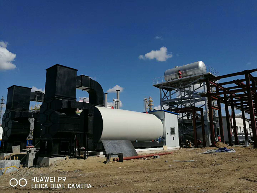
Organic heat transfer fluid heaters, also known as thermal oil heaters, are a new type of special boiler with low-pressure, high-temperature operating characteristics. Their heating temperature can reach 340℃ in the liquid phase or 400℃ in the gas phase. Organic heat transfer fluid heating can be used in various production scenarios where uniform and stable heating is required and direct flame heating is not allowed, with process heating temperatures between 150℃ and 380℃.
Horizontal oil and gas-fired organic heat transfer fluid heaters use oil and gas as fuel and thermal oil as the medium. A thermal oil circulation pump forces the medium to circulate in the liquid phase, transferring heat energy to the heat-using equipment before returning to the heater for reheating. This allows for high operating temperatures at low pressures and enables precise control of the medium's operation. The system has high thermal efficiency, and due to its modular overall installation, operation and maintenance are convenient. It is a safe, efficient, and energy-saving ideal heating equipment.
After ignition by the burner, the high-temperature flame produced enters the inner coil to form a radiation heating surface. After passing through the rear of the inner coil, it rotates 180° to enter the interlayer area between the inner and outer coils, forming a convection heating surface. Then, it enters the second interlayer area between the middle and outer coils at the front of the interlayer, and finally exits to the atmosphere through the chimney at the rear of the second interlayer area.
Performance Characteristics:
1. Obtain low-pressure, high-temperature heat transfer medium, easy to adjust, uniform heating, and can meet precise process temperatures.
2. Liquid phase circulation heating, no condensation discharge heat loss, high thermal efficiency of the heating system.
3. The volume change of the working medium due to heating and heat release and temperature rise and fall has compensation measures in the system.
4. Before circulation heating, there are technical measures to strictly control the content of air, water, and other low-volatile substances in the working medium.
Factory Conditions:
1. When the boiler leaves the factory, the main body, oil storage tank, oil-gas separator, filter, circulation pump, oil injection pump, valves, instruments, electrical control cabinet, and other parts are transported as a whole.
2. High-level expansion tank packaging
3. Factory technical documents, product packing list, and installation instructions are supplied with the boiler.
1.2 Main Components of Organic Heat Transfer Fluid Heater (Thermal Oil Heater)
Thermal Oil Boiler Body:
A. The boiler adopts a three-circle coil design (inner, middle, and outer), with a three-pass flue gas design. Compared with other domestic and international structural designs, it has the advantages of large heat transfer area, small heat dissipation loss, low exhaust gas temperature, high thermal efficiency, low fuel consumption, and long service life.
B. The boiler heat transfer coil is optimized to ensure that the thermal oil film adhering to the coil wall maintains an appropriate temperature and ensures sufficient thermal oil flow and flow rate. This not only extends the life of the heat transfer coil but also slows down the deterioration of the thermal oil quality.
C. A spiral coil is set at the rear of the boiler furnace to form a wet back, reducing the heat storage of the refractory material in the furnace and improving its own power-off protection performance.
D. The front and rear of the boiler use movable smoke box doors with a labyrinth double-seal design to ensure no smoke leakage and convenient maintenance.
E. The boiler interior uses aluminum silicate, ceramic fiber, and refractory clay for insulation, and the exterior of the furnace body uses a four-layer structure for insulation. Layers 1-3 use aluminum silicate, and the outer layer uses glass wool for enhanced insulation to minimize heat dissipation loss and improve the airtightness of the furnace body.
F. Compact structure, overall factory delivery, convenient installation and operation, and time-saving and labor-saving maintenance.
G. The thermal oil boiler flue gas waste heat recovery adapts to the boiler output and can automatically balance. The waste heat recycling is thorough, reducing the tail gas temperature and eliminating secondary waste.
H. The energy-saving device matched with the thermal oil boiler adopts various energy-saving types and can be flexibly combined to adapt to the process of the heating system, providing a complete and reliable energy-saving solution.
I. The thermal oil boiler energy-saving device has a unique design and optimized heat transfer, with significant energy-saving effects, which can improve the overall thermal efficiency of the boiler by 5% to 8%; the energy-saving device material uses corrosion-resistant materials, which can withstand flue gas corrosion and extend the service life.
J. The significant energy-saving effect of the boiler enables the entire heating system to achieve the optimal economic operation mode.
K. To ensure that the boiler efficiency reaches the optimal operating mode, our company has a boiler efficiency testing platform in the production factory, which can test thermal oil boilers of 6 million kcal and below. Customers can check on-site during factory inspection, and compare after on-site installation to ensure that the boiler's operating efficiency reaches the optimal state.
Description of the Thermal Oil Boiler Energy-Saving Scheme (Air Preheater):
When using a split-type hot air burner, the thermal oil boiler needs to be equipped with an air preheater to recover the waste heat from the boiler exhaust gas. This allows for adaptive recovery and reuse of waste heat from the flue gas. The amount of combustion-supporting air required for combustion and the amount of flue gas produced are both proportional to the combustion load. Through heat exchange in the air preheater, the combustion-supporting air can absorb the high-temperature waste heat from the flue gas discharged from the heat medium boiler in real time and directly send the recovered heat to the boiler for absorption and utilization, achieving self-matching waste heat recycling and making full use of waste heat, with the highest recovery rate (see the diagram below).
Design Goals for Energy-Saving Thermal Oil Boilers:
The exhaust gas temperature of energy-saving thermal oil boilers is reduced to below 170℃, and the recovery benefit analysis is as follows:
The exhaust gas temperature of the boiler body is approximately: 330 ℃, and the thermal efficiency of the boiler body is approximately: 85%
According to empirical data, for every 21 ℃ decrease in exhaust gas temperature, fuel can be saved by approximately 1%.
After waste heat recovery by the air preheater, the exhaust gas temperature is reduced to below 170 ℃, and the overall thermal efficiency of the boiler can reach above 92%.
Therefore, the direct benefit of flue gas waste heat recovery can save more than 7% of fuel.
Overview of the Circulation System:
For organic heat carrier furnace circulation systems, an injection method is recommended. This allows the higher-pressure medium to first pass through the organic heat carrier furnace body, resulting in lower pressure on the heat-using equipment, thus improving the safety of the heat-using equipment.
The specific loop for the organic liquid injection circulation work mainly consists of a basic circulation loop, a low-liquid loop, and a power-failure protection loop. The circulation loop's function is that the oil injection pump, through the switching of the gate valve, can inject a sufficient amount of organic liquid from outside into the oil storage tank for system operation, and can also send the organic liquid in the oil storage tank to the entire working system. It can also unload the liquid stored during furnace shutdown and maintenance into the oil tank.
After the system is filled with oil, start the circulation pump and gradually increase the temperature of the furnace body, causing the system oil temperature to continuously rise. The water, air, and low-volatile substances contained in it are then introduced into the expansion tank through a separator for removal.
After the water and other impurities in the system are removed, the system can be put into normal operation according to the basic circulation loop described above.
To ensure the safe and reliable operation of the entire organic heat carrier furnace circulation system, in addition to the organic heat carrier furnace main unit, there are also mature auxiliary circulation system equipment available for users to choose from.
Main auxiliary equipment:
a. Expansion tank: The expansion tank is used to accommodate the volumetric thermal expansion of the organic liquid at high temperatures (the oil expansion volume is 10% for every 100℃ increase in oil temperature). In addition, it also has the function of supplementing organic liquid and removing water, gas, and low-volatile substances from the system.
The expansion tank should be installed at the highest point of the system to stabilize the pressure head and prevent the organic liquid from vaporizing. The bottom of the expansion tank should be at least 1.5m higher than the highest point of the system.
The expansion tank is a pressure vessel equipped with a vent hole communicating with the atmosphere, an overflow port, and a low-level alarm and combustion interlock device to ensure the safe operation of the system.
The inventory control of the organic liquid in the expansion tank should be: when the system is at room temperature, only 1/4 of the volume is filled, while when the system is at operating temperature, it is 3/4 of the volume filled.
b. Storage tank: The volume of the storage tank should basically meet the requirements for storing the organic liquid of the entire system. It is a pressure vessel, connected to the expansion tank, and is generally located on the ground or below ground level of the entire system.
c. Filter: In addition to impurities that may be mixed into the organic liquid itself, compounds and residues will be generated during high-temperature operation. To prevent these substances from depositing on the heating surface of the furnace body or blocking the system pipes, and to maintain the normal operation of the circulation pump, a filter is installed on the piping before entering the circulation pump. The filter should be regularly cleaned of the accumulated deposits on the filter screen. During cleaning, the circulation work can be temporarily carried out through the bypass valve. After cleaning, switch back to the oil pipeline in time.
d. Separator: Used to separate air, steam, and non-condensable gases in the system and discharge them into the expansion tank for removal.
Its installation height should ensure that the horizontal inlet and outlet are at least flush with the highest point of the pipeline.
e. Circulation pump: The selection of the flow rate, head, and power of the circulation pump directly affects the operation effect of the system and determines the power consumption of the device. Considering these two aspects, the circulation pump should be determined based on the required heat load and the approximate resistance of the system through calculation and comparison. The model and lift are shown in the product list.
f. Oil injection pump: Used for oil injection and unloading. Considering that this pump is not frequently used equipment, and the amount of liquid pumped only affects the injection time, a small-capacity gear pump is used. The model and specifications are shown in the product list.
g. Oil filter (Y-type oil filter): The oil filter is used to filter and remove foreign objects from the heating system.
h. Oil-gas separator: The oil-gas separator is used to separate and remove air, water vapor, and other gases from the heating system, ensuring that the heat transfer oil operates stably in a liquid phase without gas or water.
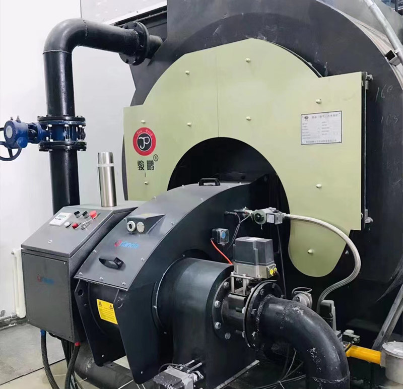
i. Burner: Used to convert fuel into high-temperature flames.
Related Products
Contact Us
Sales Tel: +86-0532-58710666
Sales Tel: +86-13335063629
After-sales Tel: +86-0532-58710332
After-sales Tel: +86-13969678003
Email: qdjp-zh@163.com
Address: Qingdao High-tech Industrial Development Zone, New Materials Group
Copyright © 2025 Qingdao Junpeng Petrochemical Equipment Manufacturing Co., Ltd